
Finding Power Quality Problems
July 27, 2021 | By Frank Healy
Using basic power quality measurements, such as volts, amps, and power factor, a technician can narrow down power-related problems to a specific source.
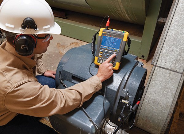
Measuring current on a three-phase motor. (Photo: Courtesy Fluke)
Troubleshooting motor issues requires isolation of the problem area before a fix can be implemented. There are three key potential sources of the problem: the motor, the load, or the motor controller—commonly a variable frequency drive (VFD). With so many possibilities, it’s important to be able to safely and efficiently identify the source to avoid downtime.
Using basic power quality measurements, such as volts, amps, and power factor, a technician can narrow down power-related problems to a specific source. Using the right tool, such as a clamp meter with the measurement calculations built in, makes the job of ruling out problem sources easier and faster.
Voltage unbalance
Overheating in three-phase motors is often a symptom of voltage unbalance, usually caused by unbalanced loads across individual phases of three-phase electrical panels, unbalanced utility supply, or deteriorating stator insulation. A good place to start is with monitoring the current drawn by the motor.
Three-phase motors should carry equal loads on each leg—the current that they draw on each phase should be about the same. Monitoring current on, say, a heat pump, 15-ton water source heat pump with a 1.5 HP, 3-phase blower motor, requires an amperage check on all three legs. This needs to be monitored over several days, up to a week, to identify any unbalance issue.
While power quality analyzers will calculate voltage unbalance for you, it is worth knowing the basics of the formula so that you understand what is involved. The calculation is straight forward with the result being the percentage unbalance. This can be used to determine the next steps in troubleshooting motor issues.
Following are the three steps in the voltage unbalance calculation:
1. Determine the average voltage (or average current)
2. Calculate the largest deviation from the average
3. Divide that maximum deviation by the average voltage (or average current) and multiply by 100%
[unbalance = (Max deviation from avg./three phase avg.) x 100%]
A manual unbalance calculation is a point-in-time determination of voltage or current unbalance.
Sags and Swells
Sags and swells represent under and over voltage, respectively, and are common in VFDs. Sags occur with sudden drops in voltage which can be caused by large inductive motors starting up, similar operations occurring in neighbouring facilities or even severe weather.
Swells occur when there is an overvoltage on the system, sometimes caused by a fault on one phase of a three-phase system, a sudden decrease in load or capacitor bank switch.
Troubleshooting overvoltage starts with a good understanding of the relationship between torque and current. Motors turn electrical energy (current) into rotational mechanical energy (torque) via magnetism. What a load demands of a motor is torque. Basically, the amount of torque supplied is proportional to the amount of current used by the motor.
When a load demands more torque and current than a motor can supply, the result is an overload condition. Overloading will cause overheating of the motor where controllers then shut the motor down rather than allowing permanent winding insulation damage to occur. Overloading is always relative to time: a high overload will trip the motor in a short time, while a lower level of overload will take longer to trip the motor.
There are two types of torque: variable and constant. Variable torque loads include fans and rotary pumps and are where the majority of load comes from in terms of energy consumption. From a troubleshooting point of view, the important thing to realize is that these variable torque loads rarely cause overload-related problems for drives.
Constant torque loads can be more challenging. Frictional or gravitational loads are constant torque loads. The key thing to understand about these loads is that they require the same level of current (more or less) at lower speeds. This can be dangerous for the motor.
Motors are usually cooled by fans built onto the rotor; when the motor slows, the fan cools less. Therefore, excessive heating can occur. The danger is that motor overload circuits are built to measure heat indirectly by measuring current (there are motors with heat sensors embedded in their stators, but these are obviously more expensive).
Harmonics
What about harmonics at the output of the drive? Wouldn’t the PWM-turned-into-sinewave current-waveform contain a lot of harmonics? Absolutely. But we don’t have to measure these. First, they don’t get into the rest of the power distribution system; they only affect the motor, causing additional heating. However, motor and drive manufacturers have addressed this by supplying higher grades of motor insulation. In those cases where a motor is retrofit with a VFD, the recommendation is that the motor full load amp be derated.
Harmonic currents flow in a circuit at multiples of the fundamental 60 hertz (Hz) frequency. Such currents are not directly indicated on multimeters and are usually not found until unusual control and equipment problems surface.
Comparing the current readings from an average-responding meter to that of a good quality true-rms meter on the same circuit will help indicate harmonic issues. The average-responding meter will indicate only the 60 hertz current and the True RMS meter will indicate a combination of 60 hertz and harmonic currents. The production and reflection of these harmonic currents back into the electrical distribution system can cause problems.
With some basic understanding, today’s professional technicians and engineers can isolate harmonic problems to their source and mitigate their effects by either replacing the offending item or installing harmonic filters.

